
What does a stator vane do between turbine rotors?
It turns the flow toward the next rotor and defines part of the stationary passage. Vane angle, throat spacing and platform geometry affect the flow reaching that rotor row.


Turbine stator vanes turn and accelerate the gas flow toward a rotating blade row. Unlike blades, they remain stationary, but their airfoils and supports experience thermal gradients, gas loading and environmental attack. Stage position, cooling design and segment arrangement shape the manufacturing problem. ForceBeyond supports custom stator vane, segment and ring supply enquiries, coordinating casting, machining and inspection against the defined component. Stage 1 NGV and inter-stage TGV remain distinct sections on this page.
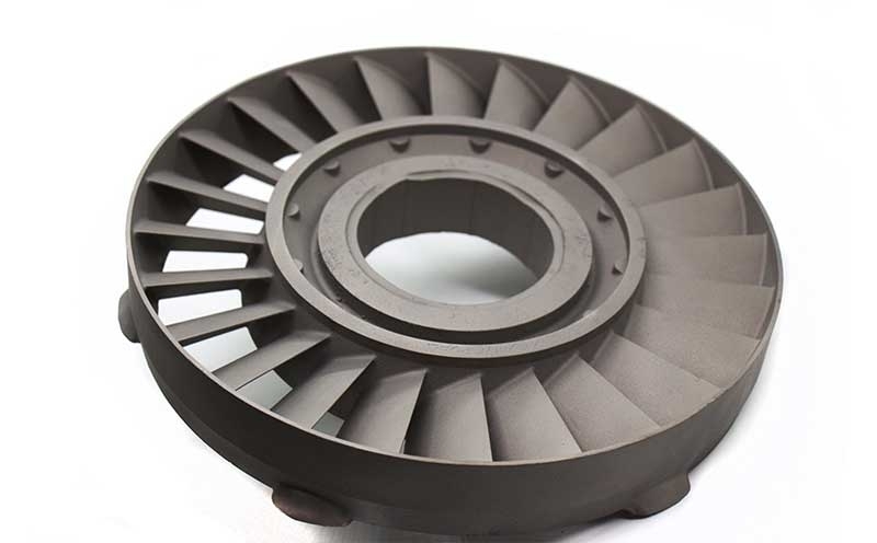
Scope a stator vane or assembly. Send the stage and assembly drawing, alloy, cooling details and required casting or finished-component scope. Request a custom quote.
NASA’s rotor/stator explanation shows the stationary row upstream of a rotor. Vane angle, adjacent-airfoil spacing and the inner/outer flow-path surfaces establish the passage seen by the gas. The mounting geometry must locate this passage while allowing the expansion assumed in the engine design. Segment and ring inspection therefore considers assembled relationships as well as the individual profile.
Throat area is a relationship between adjacent airfoils and endwalls, not a dimension of an isolated surface. Core location sets a cooled vane's local wall before coating or outlet finishing; assembled ring acceptance checks whether the intended passage and support datums survive segment positioning. The nozzle-ring guide develops those annular assembly checks in detail.
Stage 1 nozzle guide vanes receive the flow from the combustor and direct it into the first turbine rotor. Their position makes local thermal gradients, hot-gas exposure and cooling distribution central design concerns. A cooled airfoil may have an internal core-defined passage and exit holes, while platforms and attachment features locate the segment in the casing. Metal temperature depends on that complete system, not the gas temperature or alloy name alone.
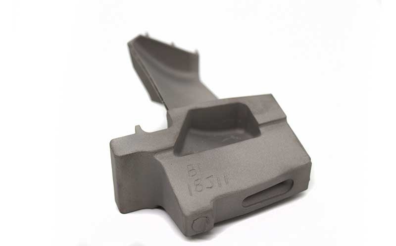
Investment casting can combine airfoil and platform features with specified internal passages. Core position influences the remaining walls; finishing and coating must preserve outlets and locating surfaces. MAR M 509 provides a cobalt-base nozzle-alloy example, while IN 738 LC represents a nickel-base cast-airfoil option. The drawing selects the grade and structure; these materials are not offered as interchangeable choices.
The inspection plan can require casting soundness, wall or passage verification, profile measurements and specified flow checks. Coating acceptance must refer to the required final state, including masked interfaces and open cooling features.
ForceBeyond can coordinate a defined NGV supply proposal covering a casting, finished vane or specified segment. A useful RFQ includes the assembly location, material and structure, cooling model, coating, dimensional acceptance and quantities. Specialized solidification and customer-approved processors require program-specific confirmation. Request a Stage 1 NGV quote.
Inter-stage turbine guide vanes condition the flow leaving one rotating row for the next. Their inlet flow, temperature distribution and pressure loading follow the upstream stage, so they should not be treated as copies of first-stage nozzles. A design may use separate vanes, supported segments or an annular diaphragm. The assembly controls passage shape, platform alignment, end gaps and interfaces with surrounding seals.
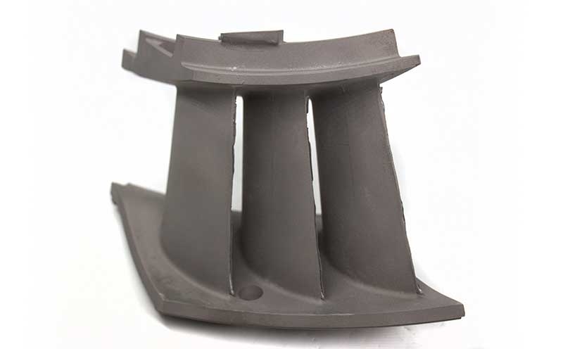
Segmented construction introduces joints and locating relationships that may be absent from an individual vane. Joining, heat treatment and final machining can change the assembled shape, so the inspection condition needs an explicit fixture or datum definition. Flow-path dimensions and mounting dimensions should refer to the same assembly state.
Nickel-alloy variants and coatings are selected for the actual inter-stage environment. Material records, joining history and part identity should remain linked through a complete ring or matched set. Required NDT and dimensional checks address the specified construction rather than the generic TGV name.
ForceBeyond can review a loose-vane, segment or complete ring supply package. The quotation needs individual and assembly drawings, the permitted joining route, alloy and treatment, inspection condition, quantities and delivery state. These define whether the next customer operation is assembly, coating or final installation acceptance. Request an inter-stage TGV quote.
| Topic | Stage 1 NGV | Inter-stage TGV |
|---|---|---|
| Incoming flow | Combustor exit flow | Flow leaving an upstream rotor. |
| Geometry priority | First-rotor inlet direction and nozzle passage | Next-stage inlet direction and assembly alignment. |
| Manufacturing focus | Cooling cores, platforms and coating where specified | Segments, ring interfaces, joints and final assembled datums. |
| Material selection | Approved grade, structure and thermal design | Approved grade for the actual stage environment. |
Stage names do not define a temperature rating, alloy substitution or common supplier approval.
Connect casting, machining and inspection with named owners for cores, tooling, coatings and release records. Source-specific qualifications and capacity need confirmation before production. The existing pictures illustrate the topics and do not certify a pictured alloy.
It turns the flow toward the next rotor and defines part of the stationary passage. Vane angle, throat spacing and platform geometry affect the flow reaching that rotor row.
The Stage 1 NGV receives combustor exit flow; an inter-stage TGV receives flow from a preceding rotor. Their thermal patterns, inlet conditions, supports and cooling arrangements depend on the specific design.
A core defines the internal passage while the outer mold defines the airfoil. Their relative position sets the remaining wall, so an acceptable external profile alone does not establish internal cooling geometry.
The supplier must control vane position, segment joints, platform alignment and the ring’s locating datums in the specified assembled state. Traceability and inspection responsibilities also extend to the assembly.
No. Stage number does not define the required material condition or life data. Alloy, casting structure, coating and acceptance requirements follow the approved design.
It should distinguish casting, finished vane, segment and complete assembly, then state cooling and coating scope, joining where applicable, required records, quantity and schedule.
Send the stage and assembly drawing, alloy, cooling details and required casting or finished-component scope.
Expand this section to review the external standards, technical organizations, and reference materials used for this page.
Explore related ForceBeyond material, process, quality, industry, and manufacturing resources.