
Does a titanium wheel enquiry always describe a hot turbine rotor?
No. It may refer to a compressor impeller or another wheel configuration. The assembly drawing and actual service function must resolve the application.


A titanium turbine wheel enquiry may concern an approved turbine rotor, a compressor impeller or another rotating wheel; the assembly drawing must resolve that function. Titanium’s low mass does not by itself qualify it for a hot gas path. Alloy, blank structure and local geometry establish the actual engineering basis. ForceBeyond supports custom titanium wheel manufacturing and supply enquiries with integral airfoils, hub, shaft interface and verification requirements treated as one scope.
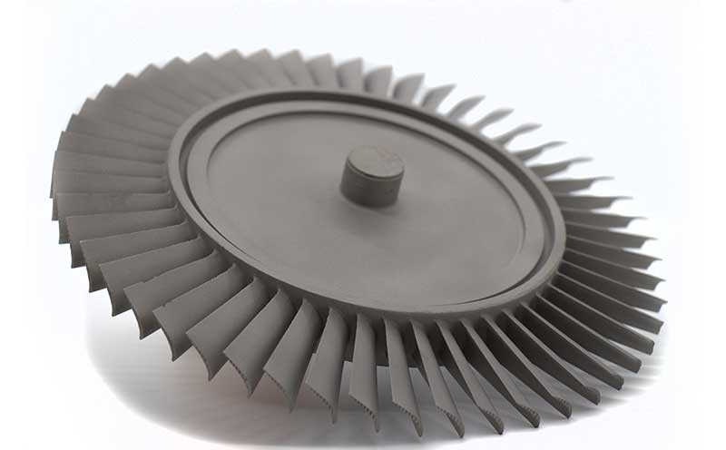
Discuss your titanium rotor component. Send the wheel and assembly drawing, actual service function, approved alloy and blank route, plus required rotor checks. Request a custom quote.
NASA’s turbine description explains extraction of work from gas by a rotor. A compressor impeller instead transfers work into the air. Their service environments and approved materials can therefore differ even when both are integral airfoil components. The actual rotor location must remain attached to the material enquiry.
ATI’s Grade 5 titanium data document compressor applications for Ti-6Al-4V. That reference does not validate a generic hot-turbine wheel or an unspecified titanium grade. Material condition and product-form data must match the approved design.
The titanium compressor impeller page is the relevant configuration when the rotor adds energy to incoming air. A turbine wheel extracts energy from hot gas. A drawing titled “titanium turbine wheel” therefore needs its rotor position, gas path and approved material before the supplier can interpret the request. ATI's compressor-oriented titanium examples cannot qualify a hot turbine wheel by analogy.
| Feature | Engineering role | Manufacturing focus |
|---|---|---|
| Hub and bore/pilot | Locates the rotor axis | Datum stability, runout and shaft-interface fit. |
| Integral airfoils | Transfers aerodynamic load | Profile, local thickness and tool access. |
| Hub-to-airfoil transitions | Carries load between sections | Fillets, surface integrity and inspection access. |
| Tip and balance features | Final rotor geometry and mass distribution | Permitted correction and final delivery state. |
The approved drawing sets actual tolerances, surface limits and verification obligations.
A forging, casting or stock-machined route has different material and allowance requirements. The permitted blank must support tool access through the passages and finishing of the hub and shaft interface. Thin airfoils can deflect under clamping or cutting loads; the process sequence needs to preserve the final shape rather than measure it only under restraint.
The existing compressor impeller resource provides related configuration context. A wheel delivered loose, joined to a shaft or as a verified rotor assembly has a different commercial and inspection boundary.
On an integral titanium impeller-like geometry, support the hub without bending thin airfoils, establish the bore or pilot as the rotation datum, and verify the final blade profile after fixture release. Tool access through narrow passages, edge finish and local hub-to-airfoil fillets affect both machining order and inspection access. The drawing determines whether a loose wheel, wheel-shaft assembly or tested rotor is actually ordered.
A NASA titanium-component investigation associated surge-related contact with ignition in one engine. This is a bounded example supporting attention to rub and contact assumptions, not a general failure prediction for titanium wheels.
The selected material and surface plan must address the actual environment. Specified edge condition, surface treatment and required NDT remain tied to the drawing. A coating cannot be assumed to make any titanium wheel acceptable for any temperature or contact event.
Runout describes geometry relative to an axis; balance addresses mass distribution. A prescribed proof or overspeed test is another obligation with its own fixture and assembly state. A wheel can meet one check without the others being established. Required methods and limits must be identified before the supply package is priced.
ForceBeyond can scope a qualified blank and finishing proposal subject to alloy-specific capability and approval confirmation. For a quote, include the material specification, final condition, rotor model, shaft interface, surface/inspection requirements, quantities and schedule. Identify joining and rotor tests explicitly when included. The wheel hub compares the other approved material topics.
No. It may refer to a compressor impeller or another wheel configuration. The assembly drawing and actual service function must resolve the application.
They determine tool and inspection access between thin integral airfoils. Stock removal and fixturing must preserve profile and transitions while establishing the final rotor axis.
No. Temperature, stress cycle, contact environment, alloy condition and approved design data remain necessary. A mass benefit is only one material-selection consideration.
Joining, assembly runout and any specified balance or rotor tests become part of the delivery scope. The quote needs the assembly drawing and acceptance state as well as the wheel geometry.
Send the wheel and assembly drawing, actual service function, approved alloy and blank route, plus required rotor checks.
Expand this section to review the external standards, technical organizations, and reference materials used for this page.
Explore related ForceBeyond material, process, quality, industry, and manufacturing resources.