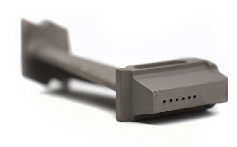
High-pressure nozzles connect hot-flow guidance with cooling geometry
A high pressure turbine nozzle guide vane is a stationary airfoil that directs
the hot gas entering a high-pressure rotor. The vane and its platforms define a
flow passage while supports locate the component in the engine. Thermal
gradients, cooling and gas loading influence the material and manufacturing plan.
ForceBeyond supports custom NGV manufacturing and supply enquiries for individual
vanes or specified segments, with casting, finishing, coating and inspection
assigned to a defined delivery scope.
Discuss your high-pressure nozzle configuration. Send the vane and
assembly drawings, alloy and structure, cooling model, coating and required delivery
condition. Request a custom
quote.
Throat and platform geometry set the installed passage
NASA’s
rotor/stator overview distinguishes stationary nozzles from rotating airfoils. The
NGV turns flow for the rotor rather than transferring blade centrifugal load. Airfoil
spacing, local throat and inner/outer platform shape establish the passage. Mounting
datums must locate those features in the assembly; an acceptable isolated profile is only
part of the installed geometry.
Cooled nozzle features need complementary inspections
NGV geometry and verification planning
Feature
Why it matters
Inspection subject
External airfoil and throat
Sets the intended gas passage
Profile and relative airfoil/platform location.
Internal passage and walls
Distributes cooling and retains load-bearing material
Specified internal geometry and wall verification.
Cooling exits
Connects passage flow with exposed surfaces
Hole condition and specified passage/flow checks.
Platforms and mounts
Locates the airfoil in the casing
Datum relationships and final coated dimensions.
Flow testing, dimensional inspection and NDT answer different questions; the component
specification selects the required combination.
Measure the installed throat against the specified platform and neighboring-airfoil
datums, then assess core-to-wall location and cooling exits separately. External profile
measurement can show a correct gas path while an internal wall is thin; a coating can
preserve the surface yet obscure an outlet. The inspection state should identify casting,
machined and coated checkpoints and the customer-approved acceptance method for each. The
Stage 1 NGV section provides the
combustor-exit application context.
Material and solidification route reflect the thermal design
IN 738 LC and MAR M 509 provide
nickel- and cobalt-base nozzle-alloy examples. They have different chemistry and
strengthening systems. A high-pressure label alone does not select either, establish a
metal-temperature limit or authorize a substitution.
Where a controlled grain or single-crystal structure is required, solidification control becomes
part of the process plan. The selected route must work with the core design, platform
geometry and thermal processing; it is not established by general investment-casting
capability.
Casting, coating and final measurement share one sequence
Core positioning controls the relationship between internal passages and external walls.
Near-net casting leaves defined stock for mounts and other interfaces. Thermal processing
and finishing then bring the vane to the required condition without losing traceability.
Coating can affect cooling exits, masking areas and final dimensions. Inspection
therefore needs a stated sequence: casting acceptance, any required internal-feature
verification, machining checks and final coating/release evidence. Repairs or joining
must follow the permitted process rather than an assumption that any defect can be
corrected.
NGV supply differs from inter-stage ring manufacture
The stator hub’s Stage 1 and TGV sections
explain different inlet environments and assembly contexts. A nozzle segment, an
individual airfoil and a complete ring or
diaphragm are distinct deliverables. Their tooling, locating fixtures and final
inspection state need separate definition.
Custom nozzle manufacturing and supplier scope
ForceBeyond can coordinate the requested casting, finishing and inspection
package. Alloy-specific source approval, special processes and capacity must be confirmed
for the program. A useful quotation also defines segment count, cooling and coating
scope, first-article records, quantities and schedule.
High Pressure Turbine Nozzle Guide Vane — Technical and Supply FAQs
What makes a high-pressure NGV different from a turbine blade?
It is stationary and guides flow into the rotor; it does not carry its own blade centrifugal load through a disk attachment. Its thermal, support and passage requirements are still component-specific.
Why is nozzle throat inspection more than an airfoil profile check?
The throat depends on neighboring airfoils and their platform/assembly position. Individual profile conformance does not establish the complete installed passage.
Can a cooling passage be accepted from the outer dimensions alone?
No. The external mold and internal core define different surfaces. The specified internal checks are needed to establish passage and wall conformance.
Can the NGV quotation include coating and final release?
A complete package can be reviewed when the coating, masking, cooling-exit and final inspection requirements are defined. Processor approvals and actual capability remain program-specific.
Request Custom High-Pressure NGV Manufacturing
Send the vane and assembly drawings, alloy and structure, cooling model, coating and required delivery condition.