
What is the purpose of an inlet guide vane?
It turns air entering the compressor toward the first rotor at the intended angle. A variable design changes this angle through its actuation system; the approved schedule belongs to the compressor design.


Compressor inlet guide vanes turn incoming air toward the first rotor at the intended angle. Fixed vanes establish a set geometry; variable vanes change angle through spindles and an actuation system. Their service is upstream of combustion, with aerodynamic, vibration, corrosion and mounting requirements distinct from hot turbine nozzles. ForceBeyond supports custom compressor guide vane manufacturing and supply, including the relationship between airfoil profile, journals, mounting features and final material condition.
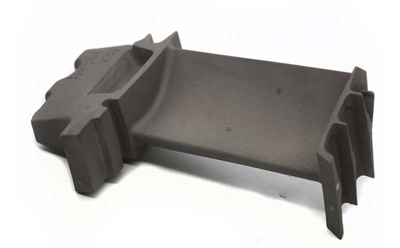
Define your guide-vane configuration. Send the vane drawing, fixed or variable arrangement, material condition and required delivery scope. Request a custom quote.
NASA’s compressor explanation places inlet guide vanes ahead of the first rotor. The vanes turn the entering air so its direction suits the rotating row. The angle schedule of a variable system is a design input; a supplier manufacturing one vane does not establish compressor performance or surge margin.
The FAA handbook distinguishes variable inlet guide vanes from variable stator vanes by their position relative to rotor rows. The exact stage and assembly reference help avoid treating these different installations as one interchangeable spare.
| Feature | Fixed vane | Variable vane |
|---|---|---|
| Airfoil location | Defined by mounting surfaces | Defined relative to spindle axis and commanded angle. |
| Interfaces | Flanges, tabs or segment supports | Journals, trunnions, lever attachment and seals where specified. |
| Inspection | Profile and mounting datums | Profile, spindle coaxiality, clocking and specified motion checks. |
| Wear context | Installation and flow exposure | Bearing/contact interfaces and actuation history as applicable. |
The actual assembly drawing determines which interfaces exist and which checks are required.
Stainless, titanium and nickel alloys offer different combinations of stiffness, mass, corrosion behavior and thermal capability. A thin vane may be sensitive to deflection during machining and service; a hard journal may need a different surface requirement than an aerodynamic face. Material selection must account for these local functions.
Outokumpu’s steel-family guide distinguishes austenitic and heat-treatable families. ATI’s titanium data provides compressor application context. Neither document supplies a universal vane alloy or an engine-level interchangeability approval.
A permitted casting, forging or stock-machined blank needs sufficient allowance for the airfoil and supports. Heat treatment and stock removal can change shape, so fixtures and intermediate measurements should relate the airfoil to the final mounting axis. Precision machining and surface finishing must preserve edges, bearing surfaces and specified coatings.
ForceBeyond can coordinate a defined vane supply scope, including final dimensional and material records. Program-specific processor approvals and capability must be confirmed. Incoming environment, cleaning chemistry and permitted surface treatments belong in the engineering requirements; a general corrosion label cannot resolve them.
An IGV sits ahead of the first rotor; a variable stator vane sits between compressor stages. Both can have an airfoil and actuation features, but stage location changes the reference assembly and inlet conditions. Starting from the approved blank, rough the profile and supports, complete prescribed thermal or surface processing, then finish the airfoil, spindle or fixed mount and inspect their mutual clocking. A fit check of a lever does not replace free-state profile measurement. The broader 718 compressor-vane term may refer to a later stage rather than an inlet IGV.
Identify the alloy and final condition, spindle or mounting geometry, airfoil model, surface requirements and required inspection. State whether bushes, levers or other hardware are included or customer supplied. Quantities and target delivery then support a comparable casting or finished-vane proposal.
It turns air entering the compressor toward the first rotor at the intended angle. A variable design changes this angle through its actuation system; the approved schedule belongs to the compressor design.
The profile must be related to the spindle axis and clocking datum. Journal fits, coaxiality, lever interface and specified movement checks can be as important as the external airfoil.
No. The FAA distinguishes them by location relative to compressor rotor rows. Use the assembly and stage reference to identify the actual part.
Yes. The supply package can define a loose vane or include specified hardware. The drawing and quote should identify excluded assembly parts and the interfaces that still require inspection.
Send the vane drawing, fixed or variable arrangement, material condition and required delivery scope.
Expand this section to review the external standards, technical organizations, and reference materials used for this page.
Explore related ForceBeyond material, process, quality, industry, and manufacturing resources.