Integral airfoils and hub create one rotor manufacturing problem
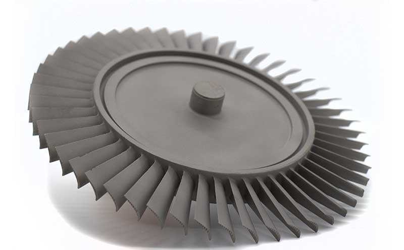
Gas turbine wheels combine a rotating hub with integral airfoils in designs such
as radial turbines and other specified rotor configurations. Gas loading,
centrifugal stress and thermal gradients act through the same component. Passage
access, hub transitions and the shaft interface affect tooling and finishing as
well as inspection. ForceBeyond supports custom wheel manufacturing and supply
enquiries with the actual rotor function and material condition defined before
selecting the production route.
Scope an integral wheel or rotor. Send the wheel model, material and
product route, shaft interface and required rotor-verification scope. Request a custom quote.
Integral geometry connects aerodynamic and rotor requirements
NASA’s
turbine overview explains how rotating airfoils extract work. In an integral wheel,
blade-to-hub transitions are part of the same piece rather than separate disk
attachments. Narrow passages can limit cutting-tool and inspection access; thin edges and
a much thicker hub can respond differently during solidification and thermal processing.
The bore, pilot, shaft or joining interface establishes the rotor axis. Airfoil
dimensions and any balance correction must be related to that axis. A loose wheel and a
wheel-shaft assembly can have different inspection and test states even when they use the
same casting.
A turbine wheel extracts work from gas through integral airfoils. A compressor impeller
adds work to air. A turbine disk accepts separate blades through attachments, while a
blisk or integrally bladed rotor combines blades and disk in one piece but may have a
different geometry and procurement route from a small wheel. These terms should not be
treated as interchangeable on a drawing. A titanium-named wheel enquiry particularly needs
rotor-location validation before material suitability is claimed.
Casting and machining address different shape constraints
Wheel production choices and design implications
Route or operation
Benefit to evaluate
Control to preserve
Near-net casting
Complex integral airfoil shape
Fill, soundness, hub-to-airfoil transitions and stock allowance.
Machining from an approved blank
Direct control of accessible features
Tool access, datum stability, local walls and surface integrity.
Thermal processing
Specified material condition
Distortion and material acceptance.
Final rotor verification
Required mass and assembly condition
Defined balance, runout and test responsibilities.
These are route-planning considerations. They do not make cast and wrought wheel
properties interchangeable.
Compare wheel alloys by function and approved condition
IN 713C and MAR M 247 are cast
nickel-base alloy references with different nominal chemistries. Their use in a
particular wheel depends on the approved structure, casting quality, thermal cycle and
life evidence. A data-sheet airfoil application does not verify an integral wheel or a
supplier.
ATI’s
Ti-6Al-4V sheet documents compressor applications. Titanium wheel enquiries must
identify whether the part is actually a compressor impeller or a rotor approved for
another environment. Low mass is not by itself a hot-gas-path qualification.
Balance, runout and overspeed are separate obligations
Dimensional runout describes geometry relative to an axis; balance addresses mass
distribution. A prescribed proof or overspeed test addresses another acceptance
requirement. None substitutes for material and surface acceptance. The required method,
limits and assembled condition must come from the rotor specification.
ForceBeyond can coordinate casting,
finishing and the specified inspection package. Grade-specific
capability, joining processes and rotor testing need explicit confirmation; they are not
implied by a generic wheel enquiry.
Define a wheel-only or wheel-shaft supply package
Include the drawing and CAD, material specification, casting or blank route, finished
shaft interfaces and critical surfaces. If joining, balance or rotor tests are included,
identify their acceptance state and responsible party. Quantities, tooling status and
schedule complete a scope suitable for a custom manufacturing quotation.
Turbine Wheels — Technical and Supply FAQs
Why is an integral turbine wheel different from a separately bladed disk?
The wheel incorporates airfoils and hub in one component. Their transitions, passages and surfaces share a manufacturing route; a separately bladed disk has additional blade-attachment interfaces.
Are runout and balance the same rotor check?
No. Runout measures geometric variation relative to a datum axis. Balance addresses mass distribution about rotation. The rotor specification determines the required state and limits for each.
Does a cast airfoil alloy data sheet qualify a wheel?
No. The wheel geometry, casting route, material condition, duty cycle and acceptance evidence still need evaluation for that design.
Should a quote include the shaft with the wheel?
Only when the requested deliverable includes it. A wheel-only order, a joined wheel-shaft assembly and a tested rotor package need different drawings, process responsibilities and release records.
Request Custom Turbine Wheel Manufacturing
Send the wheel model, material and product route, shaft interface and required rotor-verification scope.